ENGR 478 Embedded Systems Term Project
Digital piano on the STM32 NUCLEO-L476RG
A register-level embedded piano built with four push buttons, three speaker outputs, SysTick sound timing, EXTI button interrupts, and two ADC potentiometer controls.
Real-time signal path
Buttons select chords. Potentiometers control volume and octave.
Hardware Setup
Simple hardware, clear pin responsibilities
The hardware is intentionally small so the software behavior can be measured and explained clearly.
Push Buttons
PC0, PC1, PC2, and PC3 are inputs with pull-up resistors. Each press or release creates an EXTI interrupt.
Speaker Outputs
PA5, PA6, and PA7 are GPIO outputs. SysTick updates these pins to create the sound waveform.
Volume Knob
PA0 is an ADC input connected to a 10 kOhm potentiometer. It controls the duty time of the sound output.
Octave Knob
PA1 is an ADC input connected to a 10 kOhm potentiometer. It moves the selected note lower or higher.
| Pin | Direction | Project Use |
|---|---|---|
| PA5 | Output | Speaker output 1 |
| PA6 | Output | Speaker output 2 |
| PA7 | Output | Speaker output 3 |
| PC0-PC3 | Input | Push buttons through EXTI |
| PA0 | Analog input | Volume potentiometer |
| PA1 | Analog input | Octave potentiometer |
Software Flow
Main logic and interrupts are separated
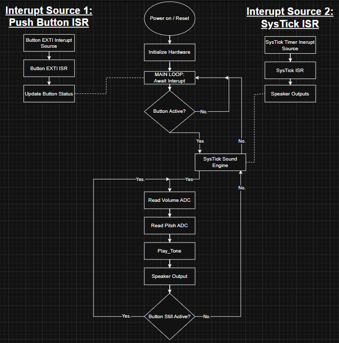
The program initializes GPIO, SysTick, EXTI, and ADC. After setup, the main loop waits
with __WFI(). Button changes are handled by EXTI interrupts, while sound
timing runs from the SysTick interrupt at 20 kHz.
- Main loop reads ADC values every 20 ms.
- EXTI interrupt updates the active button state.
- SysTick interrupt drives PA5, PA6, and PA7.
- Shared variables connect the button, ADC, and sound modules.
Design and Implementation
How the project was put together
The design was split into small parts so the project could be built, tested, and explained one step at a time. The buttons choose the chord, the ADC knobs adjust the sound, and SysTick creates the speaker waveforms.
Input Design
PC0-PC3 are button inputs. A released button reads HIGH and a pressed button reads LOW, so the EXTI interrupt can detect a press or release.
Control Design
The main loop wakes up, reads the two potentiometers every 20 ms, checks the active button, and sends the selected chord to the sound code.
Sound Design
SysTick runs at 20 kHz. Each speaker output has a counter, and the counter decides when PA5, PA6, or PA7 should change state.
Test Design
Analog Discovery 2 was used to check frequency, positive duty cycle, octave change, and button release behavior on the real output pins.
Chord Table
Each button selects a three-note chord
The software maps each button to a chord table, then the SysTick sound engine outputs the selected tones.
C Major
C - E - G
G Major
G - B - D
A Minor
A - C - E
F Major
F - A - C
Demo Video
Digital piano working on hardware
The video shows the project running on the NUCLEO-L476RG board with the buttons, speaker outputs, volume control, and octave control.
Demo Plan
What the demo verifies
The demo is organized around the main embedded concepts used in the project.
Button Response
Press each button and show that a different chord is selected.
Release Behavior
Release the button and show that the sound stops cleanly.
Volume Control
Turn the PA0 potentiometer and show the sound level changing.
Octave Control
Turn the PA1 potentiometer and show the pitch moving lower and higher.
Testing
Measured with Analog Discovery 2
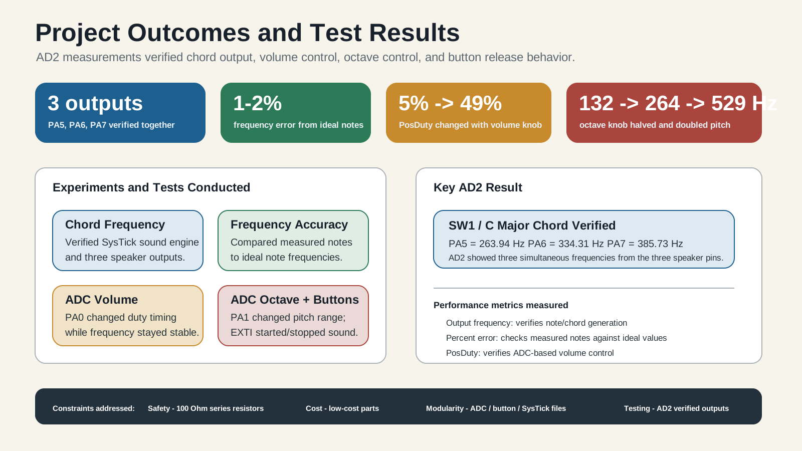
The project was tested by checking the speaker output pins, button press and release behavior, ADC volume control, and ADC octave control. The measured values show that the generated tones closely match the expected musical frequencies.
AD2 Frequency Validation
Each button produced its own chord
The speaker pins were measured with Analog Discovery 2. These readings show that each push button selected a different three-note chord on PA5, PA6, and PA7.
| Button | Chord | PA5 | PA6 | PA7 |
|---|---|---|---|---|
| SW1 | C major | 263.85 Hz | 334.36 Hz | 385.60 Hz |
| SW2 | G major | 385.85 Hz | 501.57 Hz | 590.15 Hz |
| SW3 | A minor | 436.21 Hz | 527.98 Hz | 669.27 Hz |
| SW4 | F major | 346.02 Hz | 435.85 Hz | 528.05 Hz |
AD2 Volume Validation
Volume knob changes the duty cycle
The PA0 potentiometer changes the positive duty cycle of the output waveform. This changes how loud the sound is while the note timing is still controlled by SysTick.
| Volume Setting | Button / Chord | PA5 Frequency / Duty | PA6 Frequency / Duty | PA7 Frequency / Duty |
|---|---|---|---|---|
| High | SW3 / A minor | 436.09 Hz / 49.959% | 527.85 Hz / 49.961% | 668.71 Hz / 49.847% |
| Medium | SW3 / A minor | 435.97 Hz / 23.760% | 527.98 Hz / 23.416% | 669.09 Hz / 23.000% |
| Low | C major capture | 263.94 Hz / 1.2207% | 334.36 Hz / 1.5603% | 385.85 Hz / 1.7686% |
AD2 Octave Validation
Octave knob shifts the chord frequency
The PA1 potentiometer changes the selected octave. The readings show the same chord moving lower and higher as the knob position changes.
| Octave Setting | PA5 | PA6 | PA7 |
|---|---|---|---|
| Lower Octave | 131.97 Hz | 167.15 Hz | 193.14 Hz |
| Middle Octave | 263.94 Hz | 334.26 Hz | 385.85 Hz |
| Higher Octave | 527.57 Hz | 667.97 Hz | 770.50 Hz |
| Highest Octave | 1.0022 kHz | 1.2530 kHz | 1.4317 kHz |
Firmware
How the code is organized
The project is split into small C files so each peripheral has a clear job and the full program is easy to explain.
main.c
Starts the board setup, reads the two ADC knobs, checks the active button, and calls the sound functions.
button.c
Sets PC0-PC3 as button inputs, uses EXTI interrupts, and debounces button press and release changes.
Systick_timer.c
Runs the 20 kHz sound timing, loads chord frequencies, changes volume duty time, and counts milliseconds.
ADC.c
Reads PA0 and PA1, smooths the knob values, and converts them into volume and octave settings.